This project was started out as an accessory for another crowdfunding project - a smart TFT display for Arduino called
CleO. Now,
the display itself required 150mA current, fine, but when you add a camera with its LED lights, this goes up to 250mA and if you have 1W audio playing
simultaneously, unlikely, but possible, then it would require 450mA of current at 5V in order to guarantee operation. You could the USB jack to supply
500mA power, but this doesn't leave much headroom to power other Arduino shields, so connecting a PSU to the DC jack seemed to be the answer.
This started us thinking - well, the LDO regulator on an UNO and compatible boards is rated at 1A **but** how much current can you actually take
without the regulator overheating and shutting down. We decided to measure it on a genuine UNO R3 board at 9V and 12V input, and the answer was
surprisingly low especially with a 12V supply. Our measurements and test methodology are shared with you below.
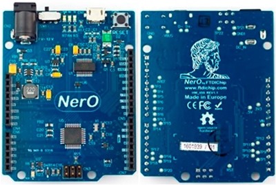
The UNO R3 is the staple of most Arduino based projects but it's been around for a number of years and many of the features have been improved for
example by Adafruit and Sparkfun who make excellent enhanced UNO compatibles. However, our additional requirements for a full 1A current without excess
heat dissipation and FCC/CE conformity led us to consider a new 3rd party UNO compatible reference design that met these requirements hence the
inspiration behind NerO. We were delighted with the results of our prototype so we decided to make it available in its own right for anyone to use.
On launch we will make the NerO schematic and pcb design files available publicly as a reference design under OSHWA ( Open Source Hardware Association )
terms and welcome the community to benefit from our original design work.
VIN Input voltage - 7V to 20V ( 9V or 12V recommended).
UNO R3 form factor.
14 Digital I/O Pins (6 PWM outputs).
6 Analog Inputs.
FTDI FT231XS USB UART interface.
Key Features
Hi-Speed
USB to one-wire interface converter
Micro USB connector
Status and PWR LEDs moved to edge of PCB - and remain visible when a shield is placed on the expansion connectors
On-Off Switch for added user convenience
FTDI FT231X USB UART (Note 1)
5V Switching regulator vs LDO regulator (Note 2)
FCC/CE certified (Note 3)
Quality product - manufactured in Europe (Note 4)
Note 1 - FT231X is one of the latest X-series family of USB UART solutions from FTDI. It has larger communication
buffers at a lower cost compared to our popular ubiquitous FT232R device. FT231X has 3.3V output levels and 5V tolerant inputs.
FTDI provide drivers for its USB bridge devices across many platforms including certified drivers for Windows, including Windows 10.
Note 2 - The NerO Buck Switcher regulator is much more energy efficient than an LDO device especially at higher Voltage inputs.
It can supply a full 1A current at 5V without breaking sweat, or anything else. Great in all circumstances where external power is
used - especially for designs with higher power requirements such as driving displays/LEDs/ Wi-Fi etc. An excellent solution for for
9V battery powered solutions, automotive ( 12V ) and POE designs as well.
Note 3 - NerO is FCC/CE certified as is the original UNO, and so is
suitable for commercial applications as well as hobbyist/maker projects. Most other compatibles are not FCC / CE certified. NerO is manufactured using
quality manufacturers and components and, despite this, is still priced at an affordable level (under $20 US) for all. Our Kickstarter backers can
enjoy a 25% or more discount on the R.R.P.
Note 4 - As mentioned above, manufacturing quality is very important to us -
so we have partnered with MikroElektronika in Europe to manufacture our NerO using their advanced SMT assembly line. We plan to show you around their
production line in a coming Project Update.
NerO Open Source Hardware Project Files - Please note, FTDI
Chip utilises Altium Designer as our hardware design tool. Please
install this tool
here
before viewing or editing the files.
Here's a few of the tests we carried out on our prototype NerO board.
Load Current Measurement
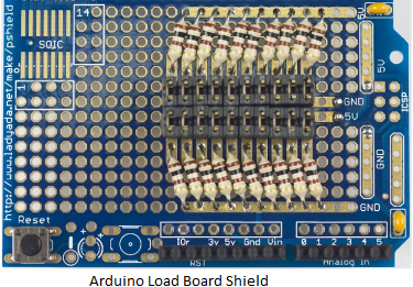
First we constructed a "load board shield" consisting of 20 x 100 ohm resistors and jumpers on each between 5V and GND.
By inserting/removing jumpers we can simulate shield load currents on the 5V rail from 0mA to 1A in 50mA increments.
Should you like to make your own and repeat the experiment, we used an AdaFruit ProtoShield v6, shown above, to make this.
Next, we measured the performance of the regulator as we increased the load current using the above board, firstly using a 9V DC supply on the DC Vin Jack,
followed by the same test but with a 12V supply.
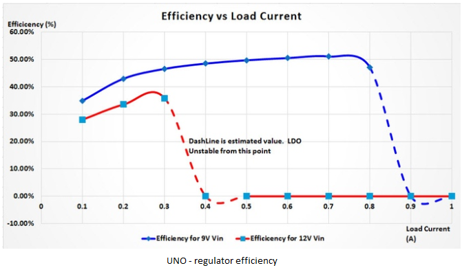
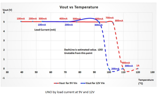
Firstly - here's the results on a genuine (made in Italy) Arduino UNO R3. With a 9V DC suppy, the regulator starts to go into thermal
shutdown at just over 700mA current draw, likewise at 12V DC it starts to go into thermal shutdown at just over 250mA current draw. However,
please note that at this stage the LDO regulator external temperature is around 95C to 110C - extremely hot and capable of reducing the lifespan of
nearby components on the board. If, for instance, we decided that a realistic maximum temperature of the regulator should be 70C, to be on the safe side,
then the maximum shield 5V current draw would be around 400mA with a 9V DC supply and under 200mA with a 12V DC supply. Food for thought!
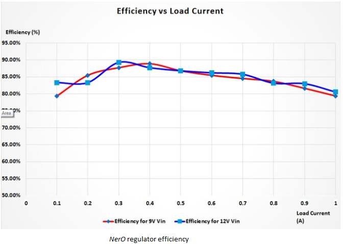
Now, we repeat the above experiment, this time with a NerO
board. At both 9V and 12V DC input, the regulator remains stable all the
way up to a full 1A load, thus meeting our design target. The regulator
temperature stays well below 60C in all conditions.
Now, lets take a look at regulator efficiency vs. load current. As expected the UNO tends to be within the 30 to 50% range depending on the load current.
NerO sits in the 80 to 90% efficiency range, again depending on the load current.
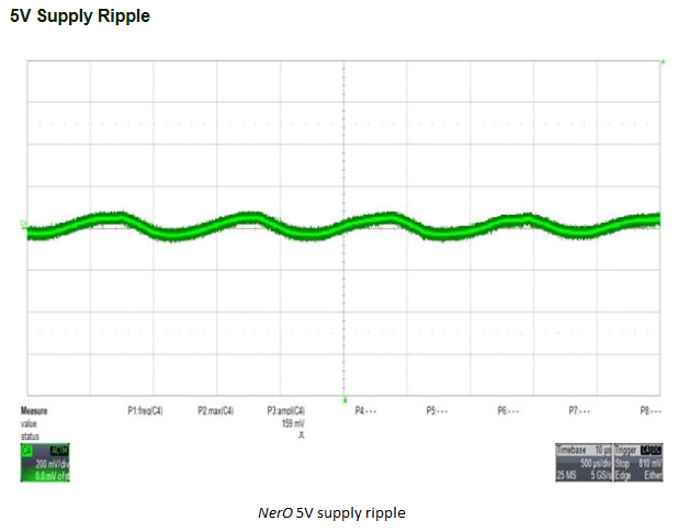
5V Supply Ripple
A measurement of the supply ripple on the output of the NerO switching regulator using an oscilloscope reveals it to be under 200mV peak to peak - perfectly adequate for driving digital logic.
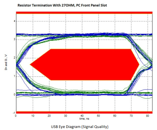
USB Signal Quality
If you've not seen one before, the above diagram is known as an Eye Diagram and is used to measure signal quality down a transmission line.
It's done using a special ( and often expensive ) oscilloscope. This ensures reliable communication across all qualified platforms.
Having one to hand, we put NerO to the test, and are pleased to say it passes well. NB - a failure is where the signal dips into the red polygon in the center of the 'eye'.
Associated Products
An FT231X provides a robust USB to UART interface with
certified driver support (including Windows 10).
Related Information
Nero was a KickStarter project, which came to live thanks to the support of our customers.
Third Party Support
FTDI Chip is working in partnership with MikroElektronika
(MikroE), specialists in the manufacture and sale of microcontroller (MCU)
development boards, accessory boards, compilers, additional software and books, to provide libraries to access the easy to use GUI based tool,
Visual TFT.


.png)